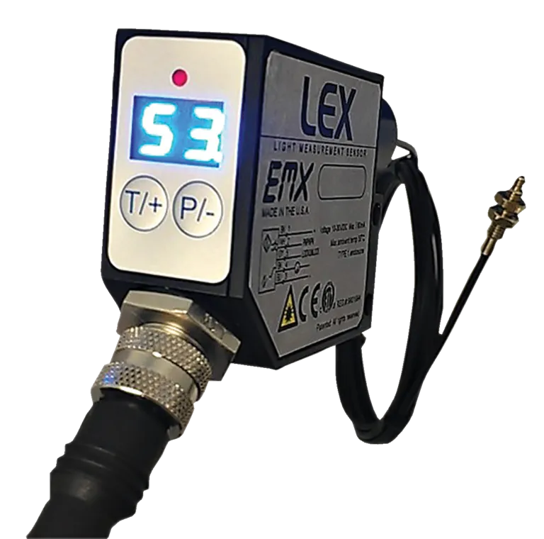
Most optical sensors on a production line work the same way. They supply their own light, aim it at a part, and read what comes back. Light intensity sensors do the opposite job. The target is the light source, and the sensor measures what that source is putting out.
That inversion changes the setup problem more than the spec sheet suggests, and it’s where most misapplications on this class of sensor begin. This guide covers what changes when the target makes its own light, the two questions that decide between EMX’s light measurement sensors, and the measurement neither one performs.
Three consequences follow, and all three show up at commissioning.
Ambient light becomes an error source. A reflected-light sensor controls its own illumination, so room light is a nuisance it can largely reject. A light measurement sensor reads external light by design and has no way to separate the target’s output from the fixture overhead. The LEX manual’s remedy is a cover or shroud over the optic. Build that into the mounting rather than adding it after the readings drift on the second shift.
Distance and angle are the sensitivity control. You can’t turn the target up or down. Moving the optic closer, farther back, or off-axis is how the reading lands in a usable part of the scale. Position the optic first and adjust gain second, because gain applied to a signal that is already pinned at the top of the range buys nothing.
The readings are comparative. Both sensors report relative values against a reference you teach them. The question they answer is whether this unit matches a known-good unit, and by how much.
Pro Tip: If a light reading drifts across a shift with no process change, shroud the optic before touching gain. Ambient contribution moves with daylight and with whatever else gets switched on nearby.
How much light, or what color the light is? Verifying that a lamp is lit, that an LED is at the right brightness, or that a backlight has not dimmed is an intensity measurement. Verifying that an indicator is the correct red rather than the correct brightness is a color measurement. The two need different receivers.
Can you get an optic to the source? A fiber tip reaches into a fixture, between components, or into a small assembly where nothing else fits. Free-space optics need a clear standoff and a source bright enough to carry across it.
A broad-spectrum receiver covering 350 to 1000 nm, fed by a 2-meter fiber optic cable with a threaded end fitting. The sensor body mounts wherever there is room and only the fiber tip has to reach the source, which is what makes it workable inside a fixture or a populated board. Relative intensity reads 00 to 99 on a two-digit display. Setup parameters are detection threshold and gain, and gain is retained when power is removed. Outputs are a discrete PNP/NPN with automatic detection plus an analog output for reading how much light rather than whether there is any. The case and fittings are metal alloy. Controls lock at the keypad by holding both buttons for three seconds until LL appears, or remotely by tying the lock line to VDC, which displays rL.
User-supplied filters over the fiber tip make it selective for a specific band.
Wrong choice when: you need to distinguish one color from another. A filter narrows what the sensor sees; it does not report which color arrived. One installation note from the manual: outputs from multiple LEX sensors must not be wired in parallel.
Separates incoming light into red, green, and blue on an RGB photodiode and compares all three against taught parameters, issuing a discrete output when the set matches. Four recognition channels drive four discrete outputs, with separate 0 to 5V analog outputs for each color component. Response time is 0.330 ms at 20 kHz sampling. Recommended sensing distance is 50 to 600 mm, depending on how bright the source is. The housing is a 316 stainless M30 barrel, 110 mm by 30 mm, IP67, with a glass window, a 12-pin connector, and a -10 to +55°C rating. Configuration runs from Windows software over RS-232 or USB, with averaging from 1 to 64 readings, teaching across 1% to 100%, and external triggering.
Wrong choice when: the source sits outside the 50 to 600 mm window, or the emitter is buried in an assembly where only a fiber will reach. The LEX-1000 needs a clear optical path at standoff. Where the check is a straightforward on, off, or dim call on a single source, four color channels is a capability that will sit unused.
Compare and Contrast: Both sensors read emitted light, and both report relative values. Choose based on what you are grading. Brightness with a hard-to-reach source points to the LEX-100. Color composition with room to stand off points to the LEX-1000.
Neither is a photometer or a colorimeter. There is no lux figure, no candela reading, and no CIE coordinate on either output. Both report a relative value against a reference you establish. If the requirement is an absolute photometric number for a specification, a certificate, or a regulatory filing, that is a different class of instrument. For inline pass and fail against a golden sample, the comparative measurement is the one you want, and it runs at line speed.
Emitters vary more than a data sheet can predict. Output falls off with age, batch differences move the numbers, and the ambient conditions at your station are specific to your station. EMX runs free sample testing on your actual part, with a report on how each sensor performed and what to change at integration.
Send in the device you need to grade and get the answer from your own light. If you are working out whether the analog output fits your controller, talk to our team before you spec it.