Four products in a catalog can all be labeled color sensors and still solve four different problems. Picking between them from spec sheets is difficult when the underlying measurement isn’t clear, because the specifications that look comparable often aren’t measuring the same thing.
The mechanism resolves it. Once you know what the sensor is physically doing when it reads a color, most of the selection questions answer themselves. This guide covers how the measurement happens, what teaching a color actually stores, the one fork that rules models in or out, and the cases where color sensing is the wrong measurement entirely.
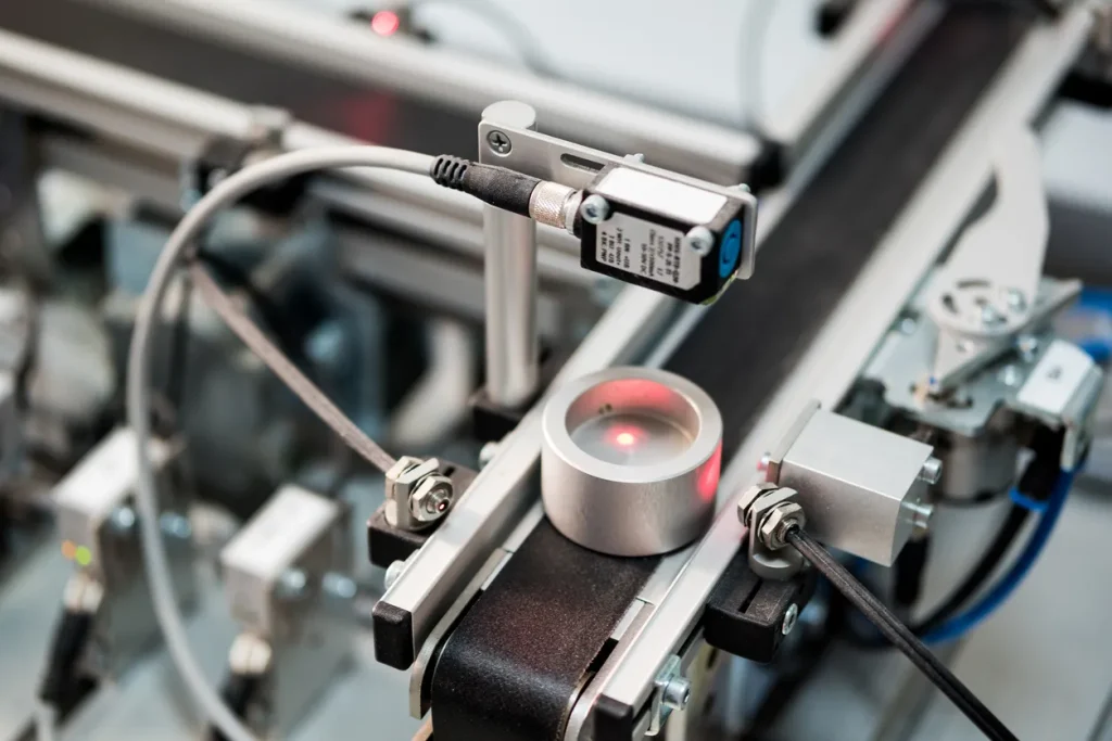
An industrial color sensor supplies its own light. A high-intensity white LED illuminates the target, and a receiver measures how much red, green, and blue comes back. Those three values become the sensor’s description of the color in view.
Supplying the illumination is what makes the reading repeatable. Ambient light in a plant changes across a shift and across seasons, and a sensor relying on it would drift with the room. By providing a known light source, the sensor controls one side of the measurement.
The values are relative rather than absolute. A color sensor reports what a surface returns under its own light at its own distance, which is why moving a sensor closer or changing the surface finish changes the numbers even though the color didn’t. This is a comparator, not a spectrophotometer, and for inline verification that’s the right instrument.
Teaching stores a reference set of RGB values from a known-good target, along with a tolerance band around it. Everything the sensor sees afterward is scored against that band.
The band is where most misapplications live. Set it too tight and normal batch variation reads as a fault, so the line generates false rejects and an operator eventually widens it past anything useful. Set it too wide and genuinely wrong parts pass. The band should be established from real production variation, which means running a range of acceptable samples during setup rather than teaching one part and hoping.
White balance adjustment addresses a second problem. When several sensors run the same check on different machines, small optical differences mean they won’t naturally agree. White balance applies correction factors to the red, green, and blue readings so all of them report the same values on the same target.
Pro Tip: If a color check is producing intermittent rejects, the tolerance band is a more likely cause than the sensor. Check what the actual production spread looks like before changing hardware.
Every other question comes after this one.
Reflected measurement bounces light off the target and reads the return. It requires an opaque surface. The ColorMax-1000 works this way, detecting color and luminosity with 20 kHz switching and an operating range up to 150 mm, with USB and RS-232 for setup and data. Painted components, molded plastics, printed packaging, textiles, and stained wood all sit here.
Transmitted measurement sends light through the target to a receiver on the other side. Translucent materials scatter reflected light in ways that make the return unreliable, so glass, films, and clear or tinted containers need this approach instead. The ColorMax VIEW is built for it, with color variation of 0.5%, 20 kHz switching, and an operating range up to 500 mm.
Determine whether your target is opaque or translucent, and half the catalog drops away.
Three applications look like color problems and aren’t.
A mark that only has to contrast with its background. Registration marks, date codes, and expiration marks need detection, not identification. The CNTX contrast sensor reads 50 grayscale levels on a numerical display with a broad-spectrum light source, so it barely cares what color the mark is. Teaching a full color channel for that job is a capability you won’t use.
A small mark moving very fast. The CMYX color mark sensor switches at 40 kHz against the ColorMax line’s 20 kHz and resolves marks down to 0.5 mm. Above a certain line speed with a small enough target, that’s the difference between catching the mark and missing it.
Something with no visible color at all. Adhesive beads, optical brighteners, and UV-readable codes have to be verified and can’t be seen. The UVX luminescence sensor detects UV response instead. No color sensor will find a target that isn’t visibly different from its background.
Dive Deeper: Browse EMX’s color sensor applications for how these run on production lines.
Everything above narrows the list. The surface in front of the sensor decides it, because gloss, texture, curvature, and batch variation all move the numbers in ways a data sheet can’t predict.
That’s what free sample testing is for. Send EMX your actual part, and the matching sensors get tested in a real-world setup with a report on how each performed and what to adjust at integration. Request a sample test and get the answer from your own material. Contact our team today to learn more.